IEC 61643 Family (Low-voltage Power SPDs)
The structure of IEC 61643, the 2025 -01/-11 split, Type 1/2/3 classification and key Iimp/In/Up parameters, plus its mapping to GB/T 18802.
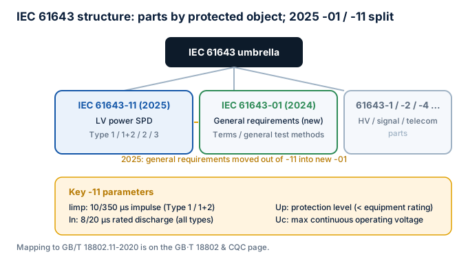
-01 / -11 split
2025: general requirements moved to -01; -11 is LV power SPD.
To textType 1/2/3
By 10/350, 8/20, no In test; different install position.
To textIimp / In / Up
Definitions and limits of the key surge parameters.
To textvs GB/T 18802
GB/T 18802.11-2020 adopts IEC 61643-11:2011; mapping.
To text1. Structure
IEC 61643 covers low-voltage SPDs of all kinds, split by the protected object:
| Part | Scope |
|---|---|
| IEC 61643-01:2024 | General requirements and test methods for all SPDs (extracted from -11 in the 2025 edition) |
| IEC 61643-11:2025 | Requirements and tests for SPDs connected to AC low-voltage power systems (Ed.2) |
| IEC 61643-12 | Selection and application principles for LV power distribution |
| IEC 61643-21 | Requirements and tests for telecom & signalling network SPDs |
| IEC 61643-22 | Selection and application for telecom & signalling networks |
| IEC 61643-31 / -32 | Test methods and selection for PV-system SPDs |
| IEC TR 61643-03:2024 | SPD testing guide (technical report) |
Edition milestone
The previous IEC 61643-11 was 2011 (with Amd1:2018). The 2025 edition (Ed.2) moves general requirements into the newly published IEC 61643-01:2024, and adds Up measurement on combined protection modes, extra durability tests for T1/T2 with follow current, updated internal-disconnector short-circuit tests, etc. Always confirm the edition you are working to.
2. Type 1 / 2 / 3 classification
Classification follows installation position and expected surge current:
- Type 1: service entrance; withstands direct-lightning 10/350 µs current, expressed by impulse current Iimp (charge);
- Type 2: distribution; withstands 8/20 µs induced / switching overvoltage, expressed by nominal discharge current In;
- Type 3: near the equipment, used with upstream stages, typically In ≤ 5 kA (8/20);
- Also Type 1+2 / 2+3 combinations, and fine protection built into equipment.
3. Key parameters
| Parameter | Meaning | Selection concern |
|---|---|---|
| Uc Max. continuous operating voltage | Voltage that can be applied continuously | Must exceed the max. operating voltage, incl. fault rise |
| In Nominal discharge current | 8/20 µs withstand (specified count) | General protection capability |
| Imax Max. discharge current | Single-shot 8/20 µs extreme | Extreme-capability margin |
| Iimp Impulse current | 10/350 µs (Type 1) | Direct-lightning withstand; also watch Ipeak |
| Up Voltage protection level | Clamping residual voltage | Must be < equipment withstand Uw (with margin) |
Ipeak is often ignored
Type 1 Iimp is usually given as charge Q and specific energy W/R, but the actual direct-lightning peak is often 3–5× the nominal. Ipeak is the real instantaneous withstand indicator — prefer products that state it explicitly.
4. Mapping to GB/T 18802
GB/T 18802 is MOD of IEC 61643. Note the adoption lag: the current Chinese power SPD is GB/T 18802.11-2020 (corresponding to IEC 61643-11:2011), not yet synced to the 2025 edition. For export or global platforms, evaluate per target market — they cannot substitute for each other.
5. Further reading
- UL 1449 — differences of the North-American system
- GB/T 18802 and CQC — domestic implementation
- Updates & Corrigenda — version tracking
1. Structure
IEC 61643 covers low-voltage SPDs of all kinds, split by the protected object:
| Part | Scope |
|---|---|
| IEC 61643-01:2024 | General requirements and test methods for all SPDs (extracted from -11 in the 2025 edition) |
| IEC 61643-11:2025 | Requirements and tests for SPDs connected to AC low-voltage power systems (Ed.2) |
| IEC 61643-12 | Selection and application principles for LV power distribution |
| IEC 61643-21 | Requirements and tests for telecom & signalling network SPDs |
| IEC 61643-22 | Selection and application for telecom & signalling networks |
| IEC 61643-31 / -32 | Test methods and selection for PV-system SPDs |
| IEC TR 61643-03:2024 | SPD testing guide (technical report) |
Edition milestone
The previous IEC 61643-11 was 2011 (with Amd1:2018). The 2025 edition (Ed.2) moves general requirements into the newly published IEC 61643-01:2024, and adds Up measurement on combined protection modes, extra durability tests for T1/T2 with follow current, updated internal-disconnector short-circuit tests, etc. Always confirm the edition you are working to.
2. Type 1 / 2 / 3 classification
Classification follows installation position and expected surge current:
- Type 1: service entrance; withstands direct-lightning 10/350 µs current, expressed by impulse current Iimp (charge);
- Type 2: distribution; withstands 8/20 µs induced / switching overvoltage, expressed by nominal discharge current In;
- Type 3: near the equipment, used with upstream stages, typically In ≤ 5 kA (8/20);
- Also Type 1+2 / 2+3 combinations, and fine protection built into equipment.
3. Key parameters
| Parameter | Meaning | Selection concern |
|---|---|---|
| Uc Max. continuous operating voltage | Voltage that can be applied continuously | Must exceed the max. operating voltage, incl. fault rise |
| In Nominal discharge current | 8/20 µs withstand (specified count) | General protection capability |
| Imax Max. discharge current | Single-shot 8/20 µs extreme | Extreme-capability margin |
| Iimp Impulse current | 10/350 µs (Type 1) | Direct-lightning withstand; also watch Ipeak |
| Up Voltage protection level | Clamping residual voltage | Must be < equipment withstand Uw (with margin) |
Ipeak is often ignored
Type 1 Iimp is usually given as charge Q and specific energy W/R, but the actual direct-lightning peak is often 3–5× the nominal. Ipeak is the real instantaneous withstand indicator — prefer products that state it explicitly.
4. Mapping to GB/T 18802
GB/T 18802 is MOD of IEC 61643. Note the adoption lag: the current Chinese power SPD is GB/T 18802.11-2020 (corresponding to IEC 61643-11:2011), not yet synced to the 2025 edition. For export or global platforms, evaluate per target market — they cannot substitute for each other.
5. Further reading
- UL 1449 — differences of the North-American system
- GB/T 18802 and CQC — domestic implementation
- Updates & Corrigenda — version tracking