TVS — Transient Voltage Suppressor Diode
Avalanche-breakdown semiconductor protector with picosecond response and precise clamping; the preferred fine overvoltage protection for power rails and signal lines.
Overview
A TVS (Transient Voltage Suppressor) is a semiconductor protector based on PN-junction avalanche breakdown. It responds extremely fast (ps), clamps precisely, and limits transient overvoltage to a chip-tolerable range within nanoseconds. Compared with MOV/GDT "coarse" protection, the TVS is the "fine scalpel" for precision devices.
Principle
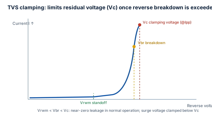
Reverse-biased, the TVS barely conducts below its breakdown voltage Vbr; beyond Vbr it enters avalanche and clamps the voltage near the maximum clamping voltage Vc, dissipating the excess energy as current.
The TVS is a clamping device (unlike the switch-type GDT), holding the voltage under Vc throughout the transient.
Key Parameters
| Parameter | Meaning |
|---|---|
| Vwm working voltage | reverse standoff, normally ≥ line operating voltage |
| Vbr breakdown voltage | voltage where conduction begins (min/max range) |
| Vc max clamping voltage | residual at peak pulse current Ipp—core selection metric |
| Ppp peak pulse power | e.g. 400 W / 600 W (10/1000 µs or 8/20 µs) |
| Ipp peak pulse current | divertible current corresponding to Ppp |
| Cj junction capacitance | high-speed lines need low values (< 1 pF) |
Selection Checklist
- Vwm ≥ max line operating voltage (incl. ripple and transient overshoot).
- Vc < protected device absolute max rating, usually with 20% margin.
- Size Ppp / Ipp by expected surge energy: convert from IEC 61000-4-5 level.
- Low Cj for high-speed signals: USB3, Ethernet, HDMI need < 1 pF or signal integrity suffers.
- Bidirectional/unidirectional: choose bidirectional for AC or bipolar signals.
Typical Applications
Power-input reverse clamp, data lines (USB/Type-C, HDMI, Ethernet), CAN/LIN automotive buses, MCU I/O, RF front-end.
Coordination with Neighboring Devices
- Divides labor with MOV/GDT: MOV/GDT for energy (coarse), TVS for speed/precision (fine) in a coarse-mid-fine cascade.
- Relation to ESD devices: ESD protectors are mostly specialized TVS arrays (see ESD).
- Common power-entry stack: GDT → MOV → TVS.
Failure Modes and Life
Solid-state, long life, almost no aging; extreme over-energy may fail short or open, so keep Ppp margin.
Standards
- IEC 61000-4-2 (ESD immunity)
- IEC 61000-4-5 (surge immunity)
- JEDEC JESD22 (TVS test methods)
Tip
Tighter clamping is not always better: forcing Vc very low means the TVS absorbs more energy and grows in size. Keep a reasonable margin under the protected device's rating.
Next
- Read ESD
- Read Overvoltage selection & coordination