Inrush NTC & PTC Thermistors
Temperature-sensitive devices that suppress turn-on inrush current—negative-temperature-coefficient (NTC) and positive-temperature-coefficient (PTC) inrush limiters.
Overview
Inrush current is an invisible killer of many devices: at power-on, a switched-mode supply, LED driver, inverter or motor sees its filter capacitor as a short and its winding/lamp as low resistance, producing a transient tens of times the steady current. Repeated shocks damage relay contacts, rectifier bridges and fuses.
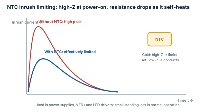
Inrush NTC and PTC inrush limiters exist precisely to suppress this class of transient.
Principle
- NTC (negative temperature coefficient): relatively high resistance at room temperature (a few to tens of ohms); at turn-on it limits inrush, then self-heats from the inrush current and its resistance falls toward zero, giving low steady-state loss. "High at start, low when steady."
- PTC inrush limiter (positive temperature coefficient): uses the PTC effect to rise in resistance on start-up overcurrent, limiting current; recovers after the fault/start clears, common in motor start and resettable limiting.
Key Parameters (NTC)
| Parameter | Meaning |
|---|---|
| R25 cold resistance | nominal at 25 ℃, sets limiting strength |
| max steady current | current it can pass long-term without overheating |
| max allowable capacitance/energy | load capacitance or single-shot energy it can suppress |
| B constant | resistance-temperature characteristic |
| dissipation factor | affects steady-state rise |
Selection Checklist
- Size R25 to limit inrush to an acceptable value: R25 ≈ (Vpeak / Iinrush_target) − line resistance.
- Steady current < rating, or the NTC stays hot, loses limiting and overheats itself.
- Note the NTC has conduction loss when hot (still several ohms); for efficiency-critical uses, bypass it with a relay later.
- For high-reliability / frequent-switching, use "NTC + relay bypass" or an active limiter.
Typical Applications
Switched-mode supplies, LED drivers, inverters, variable-frequency drives, industrial motor start, incandescent/halogen lamp drivers.
Coordination with Neighboring Devices
- NTC handles turn-on inrush; PPTC handles run-time overcurrent—different jobs, often coexisting in one device.
- No conflict with SPD/MOV: those block transient overvoltage, NTC blocks current surge.
- Frequent switching leaves the NTC hot with no limiting on re-power; needs sequencing or relay bypass.
Key reminder
An NTC stays hot and low-resistance after a fault, so frequent switching can defeat its limiting. For high reliability use "NTC + relay bypass" or an active current limiter.
Standards
- IEC 60539 (NTC thermistors)
- IEC 60738 (PTC thermistors)
- Industry application specs (power, lighting, motors)