Low-Voltage Surge-Protective MOV Selection & Application Principles — Selecting the Varistor
Per IEC 61643-332:2024 §7.1.4, the full seven sub-steps of varistor selection: MCOV, peak transient current, size/clamping, rated energy, power & TOV derating, and thermally-protected MOVs, with a 230 V / 1.25 kA worked example.

General
§7.1.4.1 selection preconditions: general guidance, maker recommendations, Annex G/H flowcharts.
ViewSet MCOV
§7.1.4.2 maximum continuous voltage: 20 % above system, 1.25× for safety standards.
ViewSet peak current
§7.1.4.3 overvoltage category I/II/III/IV → 8/20 current; check pulse life.
ViewSet size & clamp
§7.1.4.4 10/14/20 mm size comparison; each step up cuts clamp ≈10 %.
ViewRated energy
§7.1.4.5 E = K·Ve·I·τ, K from waveform table, summed in segments.
ViewPower & TOV derating
§7.1.4.6 repetitive-pulse derating, TOV fire risk, series-GDT options.
ViewThermally-protected MOV
§7.1.4.7 TMOV open mode, TOV testing, short-circuit-mode evolution.
ViewGeneral
IEC 61643-332:2024 §7.1.4.1 states up front: there is no "one formula fits all" for varistor selection — each MOV must be chosen for its specific application and the maker's recommendation. This clause (§7.1.4.2 ~ 7.1.4.7) gives general guidance and examples, not mandatory values.
| Premise | Note |
|---|---|
| General | Subclauses 7.1.4.2–7.1.4.7 are general guidelines; apply to your actual circuit |
| Basis | Use the maker's datasheet + the flow below; the standard supplies the method & criteria |
| Flowcharts | Annex G (for equipment) and Annex H (for an SPD) each give an MOV / TMOV selection flowchart |
| Caution | Do not pick a clamp voltage so low that it conducts excessively under high AC/DC line conditions — that disturbs the protected equipment, overheats the MOV and shortens life |
Link to the previous article
The prior piece "…Terms, definitions, symbols & abbreviated terms" covered the vocabulary; this piece covers the arithmetic. Re-check the symbols VM, In, Vv, Vc, PM before sizing.
Set MCOV
§7.1.4.2: The first parameter is the maximum continuous operating voltage VM (also Uc / MCOV), driven mostly by the system's supply voltage.
Two design rules:
- 20 % rule: VM should be ~20 % above the normal system voltage so the MOV does not enter the normal varistor region (mid-section of the V–I curve, Fig 5) during normal fluctuations.
- Safety 1.25× rule: Many safety standards mandate VM ≥ 1.25 × rated voltage when the MOV is across the AC supply — e.g. IEC 62368-1:2018 G.8.1.
VM worked values (230 V system):
| Equipment marking | Calculation | Result |
|---|---|---|
| Fixed 220 V AC, TT system | 230 V × 1.25 | ≥ 287.5 VAC |
| Marked range 90–250 VAC | upper 250 V × 1.25 | ≥ 313 VAC |
| Marked 120 V/230 V dual | 230 V × 1.25 | ≈ 288 VAC |
| Marked 100–240 VAC | upper 240 V × 1.25 | = 300 VAC |
Pitfalls
- Read the nameplate voltage expression: fixed (120/230 V) vs range (90–264 V) are handled differently; for a range take the upper limit × 1.25.
- When 10 % fluctuation is included (e.g. 90–264 VAC already spans it), compute MCOV from the post-fluctuation peak (264 V) × 1.25.
Set peak current
§7.1.4.3: Determine the peak transient current the MOV must ride, from the system transient level. For mains-energized equipment, use IEC 60664-1 overvoltage categories (OVC).
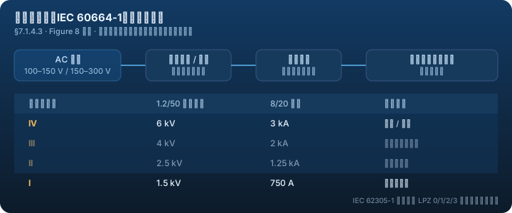
OVC → transient voltage (1.2/50) for >150 V–≤300 V mains:
| OVC | Typical equipment | 1.2/50 withstand | 8/20 current (2 Ω gen.) |
|---|---|---|---|
| IV | origin: meters, primary OCP, ripple control | 6 kV | 3 kA |
| III | fixed installs, high-reliability | 4 kV | 2 kA |
| II | consuming equipment (appliances, tools) | 2.5 kV | 1.25 kA |
| I | no direct mains connection | 1.5 kV | 750 A |
Key conversion: with a 2 Ω fictitious source impedance, the MOV's clamping voltage pulls the actual peak current down — so "category current" and "current the MOV actually sees" differ:
| OVC | Generator 8/20 current | Actual 8/20 at the MOV (after clamping) |
|---|---|---|
| IV | 3 kA | 2.5 kA |
| III | 2 kA | 1.5 kA |
| II | 1.25 kA | 1 kA |
| I | 750 A | 500 A |
Pulse-life check: a category transient is not one-off; it can recur over the equipment life. Use the "current vs repetitions" curve (Fig 9) to confirm the MOV survives the expected count. An 8/20 pulse, owing to its slow front, behaves like a 20 µs rectangular pulse.
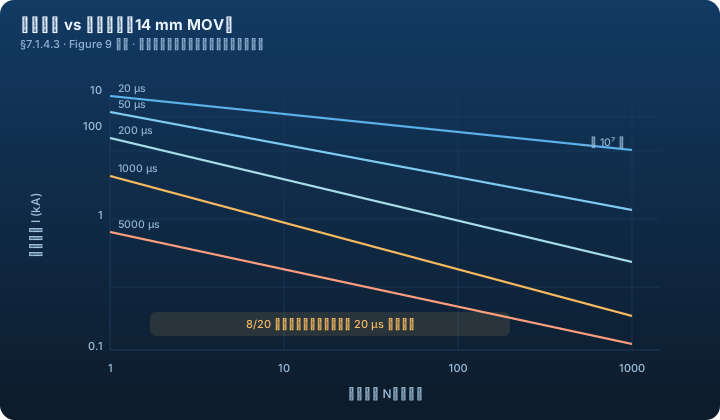
Worked example (230 V, OVC II): IEC 60664-1 needs 1.2/50 withstand 2.5 kV; IEC 61051-2 needs the MOV to ride a 1.2/50→8/20 combination pulse of 2.5 kV / 1.25 kA. Pulse width 20 µs, 1.25 kA → Fig 9 shows a 14 mm MOV survives about 7–8 pulses; for more, use a larger size.
Set size & clamp
§7.1.4.4: With VM and peak 8/20 current set, choose the MOV size (diameter), which sets clamping. If the downstream part (transformer, capacitor, etc.) has a max withstand, a larger MOV gives a lower peak voltage at a given current — each size step up cuts the clamp ≈10 % (Fig 10).
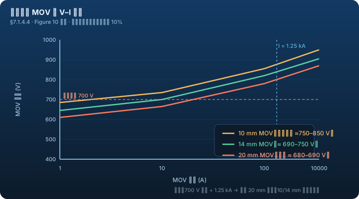
10 / 14 / 20 mm comparison (downstream limit 700 V, max 1.25 kA):
| MOV size | Clamp (approx) | Meets 700 V downstream? |
|---|---|---|
| 20 mm | 680–690 V | ✅ yes |
| 14 mm | ≈ 850 V | ❌ too high |
| 10 mm | ≈ 750 V | ❌ too high |
Rule of thumb
In most cases the size set by "VM + peak 8/20 current" is sufficient. Only when there is a hard downstream withstand limit do you need a bigger size or a parallel arrangement.
Rated energy
§7.1.4.5: Beyond the first three steps, cross-check with the MOV's rated energy — compare rated energy against the real impulse energy at the end application.
Energy estimate:
E = K · Ve · I · τ
| Symbol | Meaning |
|---|---|
| E | MOV rated energy (J) |
| I | peak current |
| τ | pulse duration |
| Ve | resulting clamp voltage |
| K | constant set by the waveform (table lookup) |
K corresponds to the current waveform only (assumes the varistor voltage is near-constant during the impulse); see the K table (Fig 11). Complex waveforms are segmented and summed.
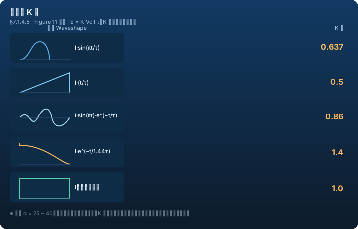
Worked example (100 A, 5/50 exponential): split into two segments —
- 0–5 µs: E₁ = K·Ve·I·τ = 0.5 × Ve × 100 A × 5 µs
- 5–50 µs: E₂ = 1.4 × Ve × 50 A × 45 µs
- Etotal = E₁ + E₂
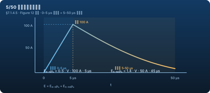
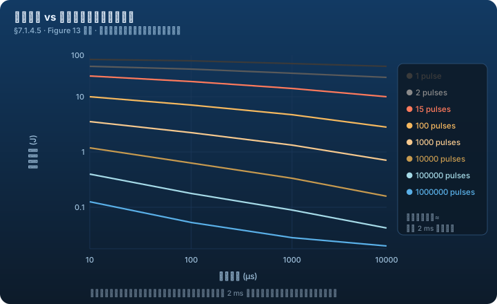
Fig 13 shows the single-impulse energy line is roughly constant over a wide pulse-width range and close to the datasheet 2 ms rated energy (this curve is usually not printed in the datasheet — for information only).
Power & TOV derating
§7.1.6: impulse type (single / repetitive) and duration affect the MOV's power-dissipation capability, split into three sub-items.
① Impulse requirements (7.1.4.6.1) - Single impulse: judge by MOV thermal capacity (≈ rated energy in joules); but the quoted energy is the single-event value — derate for repetition. - Repetitive: with cooling between events, the 10-repetition event energy is about 30 % of the single value. - Per CIGRE 549, a flash with multiple strokes + continuing current is treated as a single event carrying the total energy of its parts. - Repetitive pulses: current rating falls as the count rises, and clamping voltage falls with it; longer pulse width also lowers the current rating.
② TOV requirements (7.1.4.6.2) - A wrong/aged MOV, or a TOV event, can cause a fire when the MOV is straight across the source. TOV is a distribution fault that raises the supply above nominal. - IEC 60364-4-44:2007 Clause 442 lists TOV L-N/L-E/N-E ratings for TN/TT/IT; IEC 61643-11 Annex I adds North American & Japanese TOV tests. - Worst-case TOV at 230 V: ~AC 1500 V for 0.2 s; ~AC 400 V for both 5 s and 120 min. - Mitigation: series a GDT whose DC sparkover exceeds the source peak to stop continuous MOV dissipation. For L-E/N-E, IEC 62368-1 requires a high-voltage GDT in series with the MOV in IT equipment, which removes the 61643-11 TOV test requirement; two MOVs in series across L-N is one way to pass the 62368-1 single-fault test.
③ Parameters (7.1.4.6.3) - Where the inter-pulse interval is known, use average dissipation power: total = base dissipation P0 (normal/leakage state) + the mean of periodic energy absorption. - P0 = PM − E/T (E = single-pulse energy, T = interval, PM = maker's rated average dissipation power). - Solving for T gives the minimum interval Tmin before re-applying energy without exceeding PM.
Rules
- Never run an MOV permanently near PM; it is not for "static" dissipation (voltage regulation, TOV) — that shortens life.
- Sustained overvoltages of tens of seconds need separate protection: raise the chosen MOV voltage, or series a high-voltage GDT.
- Do not re-apply a near-limit pulse: after one 4000 A 8/20, you cannot take another 4000 A 8/20 no matter how long the gap (Fig 9).
Thermally-protected MOV
§7.1.4.7: A thermally-protected MOV (TMOV) = an MOV in series with a thermally operated link / thermal cut-off (TCO), usually supplied as one integrated component, sometimes as separate parts.
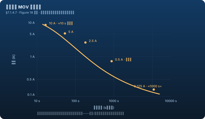
| Point | Note |
|---|---|
| Characterization | Shown as a "current vs series-link open-time" curve |
| Open mode | An end-of-life MOV is disconnected (open-circuit); but once it opens, the equipment is left unprotected |
| Short-circuit mode (emerging) | For power SPDs, a "short-circuit mode" is being developed: the SPD is shorted out so the local fuse/breaker operates — favours protection continuity at the cost of some supply continuity (note for critical apps) |
| GDT precedent | The same shorting idea already exists for telecom GDTs protecting equipment from a power fault reaching the telecom line |
TOV test requirements: AC SPDs must pass TOV tests per IEC 61643-11:2011 §8.3.8.1/8.3.8.2; IEC 62368-1 uses the same 61643-11 TOV tests for equipment MOVs across the AC supply. A TMOV may terminate current during a TOV overload, but the thermal link must open hazardlessly at the TOV voltage. IEC 62368-1:2018 G.8.2.2 varistor overload test (2× mains) is one option for TMOV use.
TMOV sizing rule of thumb (§7.2.2, for reference)
- Permanently connected (UL 1449 Type 1/2): use 25 mm or larger TMOV; must pass the 10 A limited-current TOV and 10/20 kA nominal discharge test.
- Cord connected: typically 14 / 18 / 20 mm; must pass the 5 A limited-current TOV and at least 15 impulses at 3 kA.
Next Steps
- Previous: MOV selection principles — terms, definitions, symbols & abbreviations
- Device library: MOV · TMOV · SPD
- Same domain: Overvoltage selection & coordination · Overcurrent selection