Low-Voltage Surge-Protective MOV Selection & Application Principles
Per IEC 61643-332:2024, the terms, definitions, symbols and abbreviations of metal oxide varistors (MOV), plus a walk-through of the three V-I regions that underpin varistor selection.

Standard at a Glance
Scope of IEC 61643-332:2024, intended MOVs, and the normative references.
ViewTerms & Definitions
The 14 Ratings / Characteristics definitions, fully tabulated.
ViewSymbols & Abbreviations
MOV and thermally-protected MOV symbols; 12 abbreviated terms.
ViewV-I Characteristic
Leakage / normal-varistor / upturn regions on the log-log curve.
ViewSelection in 5 Steps
MCOV → peak transient current → size/clamping → energy → derating.
ViewStandard at a Glance
IEC 61643-332:2024 (Edition 1.0, 2024-04) is the MOV-specific part of the IEC 61643 "Components for low-voltage surge protection" family. Its theme is selection and application principles for varistors. It does not define SPD type classification or test methods (that is the job of -01 / -11); instead it tells you how to pick and wire an MOV, how it fails, and how its terms should be used consistently.
| Dimension | Content |
|---|---|
| Scope | Two-electrode MOVs up to 1000 V AC or 1500 V DC on power / telecom / signalling lines, with or without disconnectors (thermal cut-offs) |
| Out of scope | Assemblies that contain MOVs, and their influence on the MOV's characteristics |
| Device type | Specifically the zinc-oxide (ZnO) MOV, a.k.a. the "varistor / VDR" |
| Goal | Unified terminology & symbols + an actionable selection method + safety and failure cautions |
Normative references (you will keep cross-checking these while selecting):
- IEC 60664-1:2020 — overvoltage categories (I/II/III/IV) and insulation coordination, sets the transient levels
- IEC 61051-1:2018 / -2:2021 — generic / sectional specs for equipment varistors; source of nonlinearity-index, energy and life definitions
- IEC 61643-11:2011 — low-voltage power SPD requirements & tests; source of Iimp / Imax
- IEC 61643-331:2020 — MOV performance & test methods (most of this part's terms are lifted from 331)
- IEC 62368-1:2023 — AV/ICT safety; mandates MOV MCOV ≥ 1.25 × rated voltage, etc.
One-line positioning
When sizing an SPD or aligning device-library specs: -11 tells you which tests the SPD must pass; -332 tells you how to pick the MOV inside it. Read them together.
Terms & Definitions (§3.1)
§3 of IEC 61643-332 splits terms into two groups: Ratings (§3.1.1) and Characteristics (§3.1.2) — 14 definitions in total. This is the "dictionary" for any selection calculation.
3.1.1 Ratings
| Symbol | Name | Definition | Source |
|---|---|---|---|
| — | rating | The limiting value/condition beyond which the MOV may be damaged; may be a maximum or a minimum | this part 3.1.1.1 |
| I1TM | single-impulse [transient] maximum current | Rated maximum current for a single impulse of specified waveform | IEC 61643-331 3.1.1.2 |
| In | nominal discharge current | Crest value of current through the MOV with an 8/20 waveshape | IEC 61643-331 3.1.1.3 |
| VM | maximum continuous voltage | Max continuously applicable voltage at a specified temperature; also called Uc or MCOV | IEC 61643-331 3.1.1.7 |
| VM(AC) | maximum continuous AC voltage | Max RMS power-frequency (THD < 5 %) continuous voltage | IEC 61643-331 3.1.1.8 |
| VM(DC) | maximum continuous DC voltage | Max continuous DC voltage | IEC 61643-331 3.1.1.9 |
| Imax | maximum discharge current | Crest value with an 8/20 waveshape, equal to or greater than In | IEC 61643-11 3.1.48 |
| Iimp | impulse discharge current, class I test | Crest value with specified charge Q, energy WIR, in specified time | IEC 61643-11 3.1.10 |
| PM | rated average dissipation power | Max average repetitive-pulse dissipation at 25 °C ambient | IEC 61051-1 3.23 |
3.1.2 Characteristics
| Symbol | Name | Definition | Source |
|---|---|---|---|
| — | characteristics | Inherent, measurable properties of the MOV | IEC 61643-331 3.1.2.1 |
| Io | standby current | Current at VM; below VM it is called leakage current | IEC 61643-331 3.1.2.2 |
| Vv | varistor voltage | Voltage at a specified current (typically 1 mA); if the maker is silent, 1 mA DC for 20–100 ms | IEC 61643-331 3.1.2.3 |
| Vc | clamping voltage | Peak voltage at class current ICLs and a specified waveform | this part 3.1.2.4 |
| ICLs | class current | For an 8/20 pulse, 100 repetitions at 30 s intervals: 1/10 of the maximum peak current | IEC 61051-1 3.21 |
| Cv | capacitance | Terminal capacitance at a specified frequency, voltage, time | IEC 61643-331 3.1.2.6 |
| SPD | surge protective device | A device with at least one non-linear element that limits surge voltages and diverts surge currents | IEC 61643-11 3.1.1 |
| SPC | surge protective component | Discrete component whose primary role is to divert/limit overvoltage & overcurrent; e.g. MOV, GDT, SIT, ABD, thyristor | this part 3.1.2.8 |
| MOV | metal oxide varistor | Non-linear resistor of sintered metal oxides whose conductance rises rapidly with voltage; a.k.a. VDR | IEC 61643-331 3.1.2.7 |
| thermally protected MOV | — | A varistor with a series non-resettable element that disconnects it on overheating | IEC 61643-331 3.1.2.8 |
| γ | nonlinearity current index | γ = log₁₀(I₁/I₂) / log₁₀(U₁/U₂); always < 1 | IEC 61051-1 3.4 |
| α | nonlinearity voltage index | Reciprocal of γ; always > 1; commonly written α | IEC 61051-1 3.5 |
| IAc | AC standby current | Current at the maximum continuous AC voltage VM(AC) | this part 3.1.2.13 |
| IDc | DC standby current | Current at the maximum continuous DC voltage VM(DC) | IEC 61643-331 3.1.2.9 |
Suggested reading order
Work ratings → characteristics: first VM (can it run continuously), In/Imax (can it ride a surge), then Vv/Vc (what it clamps to), and finally Io (idle heating).
Symbols & Abbreviated Terms (§3.2)
3.2.1 Circuit symbols
- MOV: Figure 2 shows the standard IEC two-electrode symbol (a rectangular body with a diagonal break, signalling a non-linear resistor) — distinct from GDT / TVS.
- Thermally-protected MOV: Figure 3 adds an optional monitor lead terminal so the thermal cut-off action can be reported to upstream control / alarm circuitry.
Note: IEC 60027 reserves V and v for voltage, but in the MOV field Vv and Vc are so entrenched that this part explicitly prefers them over u.
3.2.2 Abbreviated terms
| Abbrev. | Full | CN |
|---|---|---|
| ESD | Electrostatic Discharge | 静电放电 |
| GDT | Gas Discharge Tube | 气体放电管 |
| IC | Integrated Circuit | 集成电路 |
| IT | (French) Isolé-Terre | isolated-earth system |
| MCOV | Maximum Continuous Operating Voltage | 最大连续工作电压 |
| MOV | Metal Oxide Varistor | 金属氧化物压敏电阻 |
| SMD | Surface Mount Device | 表面贴装器件 |
| SPC | Surge Protective Component | 浪涌保护组件 |
| SPD | Surge Protective Device | 浪涌保护器 |
| TCO | Thermal Cut Off | 热脱扣 |
| TOV | Temporary Overvoltage | 暂态过电压 |
| TN / TT | Terre-Neutre / Terre-Terre | earth-neutral / earth-earth |
V-I Characteristic: Three Regions (§6.1, Figure 5)
IEC 61643-332 §6 plots the MOV V-I curve (log-log, one conduction direction; the reverse is symmetric) in Figure 5. The three regions are the key to understanding "varistor".
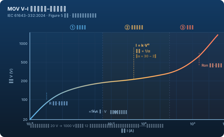
| Region | Electrical behaviour | Engineering meaning |
|---|---|---|
| ① Leakage region | Terminal voltage < Vv; the non-linear resistor Rx is high-ohmic, the parallel leakage Roff dominates | The long-term working point should sit here; Roff sets the idle standby power Io |
| ② Normal varistor operation | Rx collapses; voltage stays nearly flat while current climbs orders of magnitude as I = k·Vα | This is the "varistor" effect — a tiny voltage change trades for a huge current shunt |
| ③ Upturn region | At large currents the series Ron appears and voltage rises again | Near short-circuit; the limit-current capability |
Equivalent circuit (Fig 6): in the R-C-L model, lead inductance L causes voltage overshoot on steep fronts, terminal capacitance C makes the AC-state current exceed the DC standby current, and series Ron sets the upturn-region slope.
Selection in 5 Steps (§7.1.4)
The standard breaks "pick a suitable MOV" into five executable steps. This section is the operational basis for the later selection article:
- Set MCOV / VM: about 20 % above the normal system voltage; where IEC 62368-1 G.8.1 applies, VM ≥ 1.25 × rated.
- Set peak transient current: per IEC 60664-1 overvoltage category, 8/20 current 500 A (cat I) → 1 kA (II) → 1.5 kA (III) → 2.5 kA (IV).
- Set size, set clamping: 10 mm / 14 mm / 20 mm — each step up reduces clamp ≈10 %. E.g. 700 V downstream, 1.25 kA max → 20 mm gives ≈680–690 V; 14 mm gives ≈850 V, unsuitable.
- Check rated energy: E = K · Ve · I · τ, K from the waveform table (5/50 exponential ≈ 0.5×0.5 + 1.4×0.45, summed in segments).
- Power / derating: repetitive pulses derate (≈30 % of single-event energy at 10 reps); derate for TOV; never run the MOV long-term at VM — for sustained overvoltage, series a GDT.
Common pitfalls
- Treating "MCOV 20 % above normal" as the only rule and ignoring IEC 62368-1, which can demand 1.25 ×;
- Reading only Vv and not Vc — they are measured differently (1 mA vs class current) and must be verified independently;
- Describing MOV failure as a "safe failure mode" — the standard explicitly discourages this; use the three concrete terms: short-circuit / degradation / open-circuit + high clamp.
Next Steps
- Device library: MOV · TMOV · SPD
- Same domain: Overvoltage selection & coordination · Overcurrent selection · Thermal & surge-limiting
- Related standard: IEC 61643 series (-01 / -11)